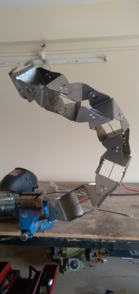
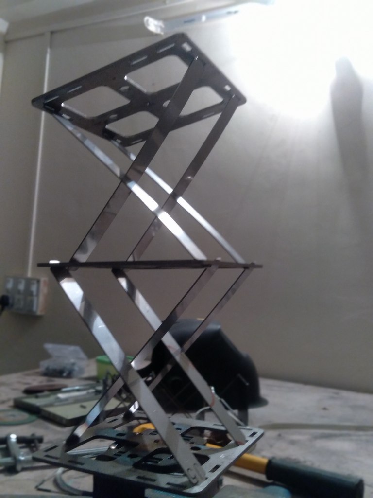
From the previous post, i have been working on the idea of bistable joints. As you can see that Prototype #5 for the first testing of the idea. I have tried a few others meanwhile.
In aluminium
In MS. it is too heavy, but the concept works.
A blind rivet limits the 2 elements from going beyond the extreme positions
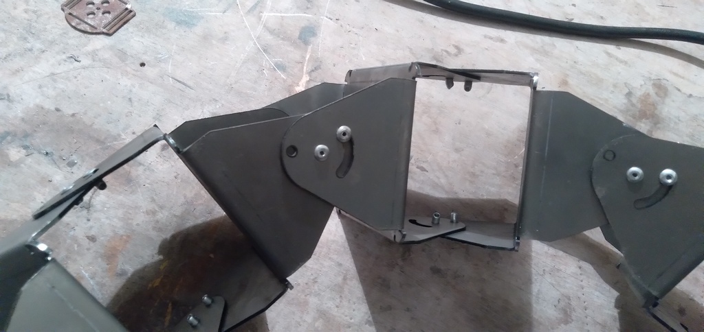
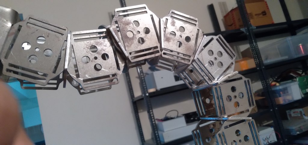
Some shapes…
Same piece, but locked in a different shape.
Another shape.
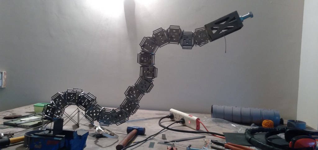
These worked, but then they didn’t. Here are the challenges:
The joints broke with the tension and weight. Learning – don’t use pop rivets for joints!!!!
Aluminium is better than MS, because it makes the structure so much lighter. However welding in aluminium is not easy.
The joints and structure flexes quite a bit, and so it does not maintain shape under the tensioning system. The whole point is lost if you tension the steel cable but then the elements flex it out. No wonder it could not hold its own weight.
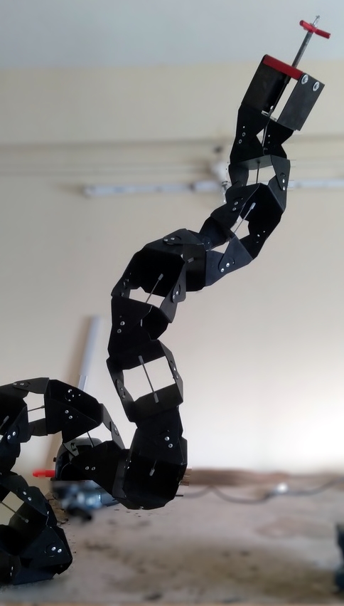
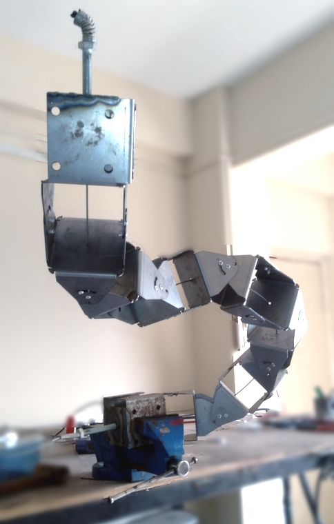
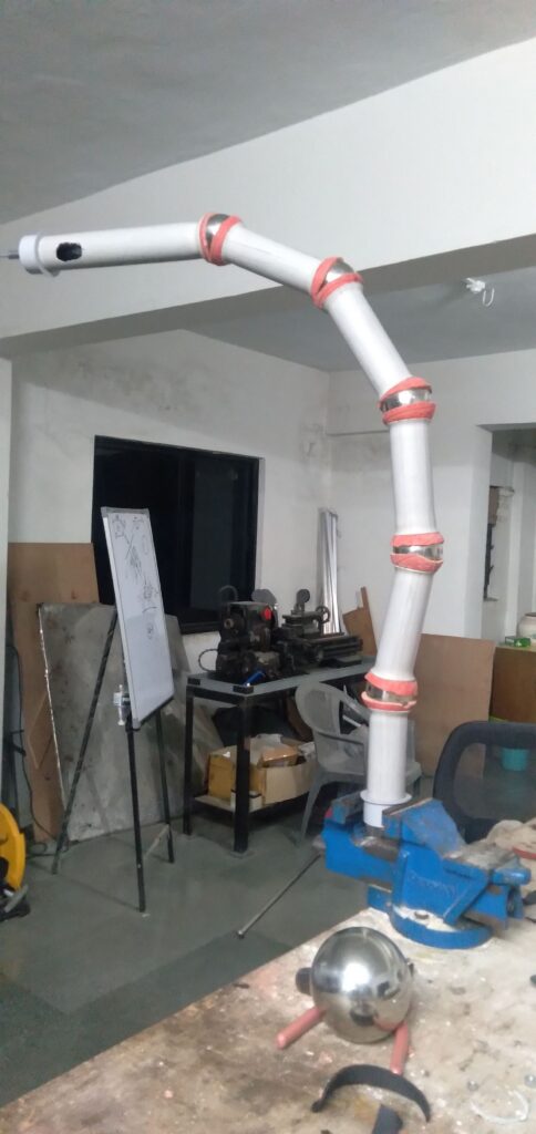
So, after a long gap of thought paralysis (1 year) I reattempted what i call the 16th Prototype. It is made out of cylinders, rather than sheet metal. Here’s why:
Cyclinders look nicer than industrial looking sheet metal works. Note that this is an important feature if it has to be used as a home furniture!
Cylinders are available, and common. One does not need to resort to laser cut pieces and machinery in this way, thus making the design more accessible as an open-source design.
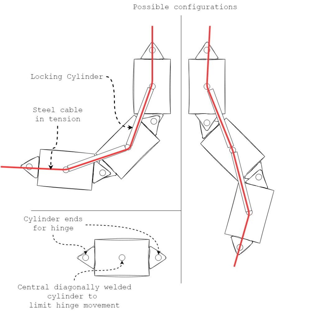
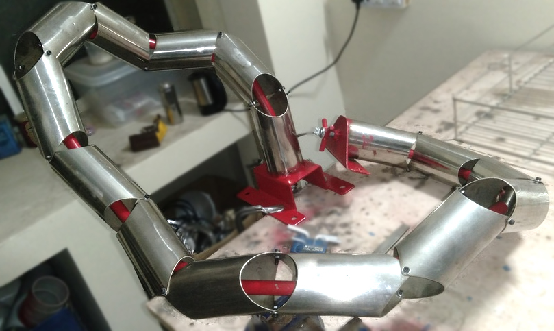
A technique of bistable elements mechanism was invented using cylinders and regular fabrication workshop. Illustrated here.
Prototype #16 – main mechanism
Each bistable section has 4 features:
2 main cylinders,
A hinge comprising of extended edges of the 2 main cyclinder. Note that there is no pin passing through to the other side, so central portion of the hinge piece is free.
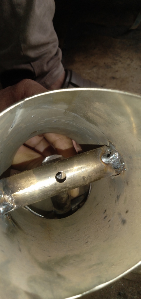
Another cylinder of small diameter diagonally welded into the main cyclinders. There is also a hole at the center of the cylinder’s length through which the steel cable passes.
A 4th cylinder through which the steel cable passes and which limits the bistable system in either extremes of the movement.
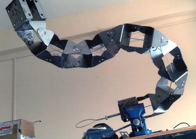
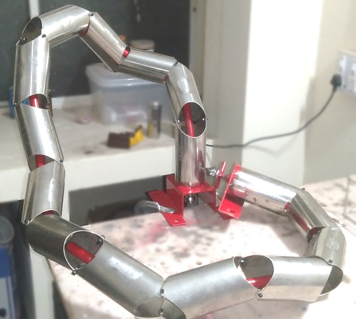
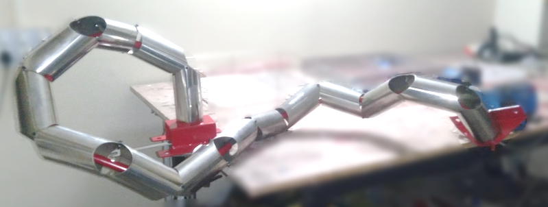
Here is how it looks after assembly:
Failures
Each main cylinder has 2 different axes for the hinges at both the ends. This allows for the stand to take on any shape in 3D. However, this makes it difficult for the central locking cylinder to lock on to the diametrically welded inner cylinder.
The length of the inner cable guide and locking cylinder was not accurate, hence the locking was not happening.
The tightening system needs to be worked with. It was too hard to tension the system.
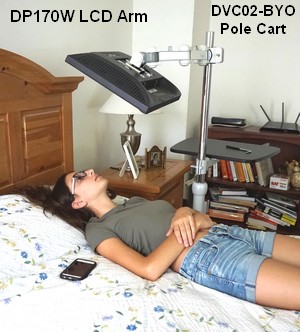
Cameras and lighting equipments often need to be positioned arbitrarily in space for optimum photographic effect. Similar need is identified for persons who are bed-ridden and need to place their laptops or communication devices in the right positions. Such a user may need to access the laptop while in either supine or lateral recumbent positions. One such need was expressed by a client of NISH, Trivandrum. The client (young male with spinal cord injury and who is bed-ridden) struggled to find the right device to hold his laptop at the right position for optimum visibility and use. This paper discusses attempts to create a generic laptop mount which offers lockable articulation needed for optimum positioning. Existing market solutions are discussed first, followed by identified engineering constraints and challenges of this project. Prototypes designed by the author are discussed next, concluded by open challenges yet to be solved in this project.
Some existing products and their constraints are discussed here (non-exhaustive)
Overhead wall arms for monitors – These are costly to begin with as they are meant for hospital settings. Even if this option is used, the monitor mounts will need to be modified to hold a laptop, incurring additional costs, voiding guarantees, etc.
Monitor mounts – These are affordable options with wall mount, ceiling mount as well as table mount options. However, they have lower length of reach and thus may have limited applicability. Another example is the laptop mount. But these are not designed for bed use.
Photographic equipment arms (Manfrotto’s Magic arm, generic adjustable arm) – These can be used but they may not be able to carry the weight of the laptop at the long distances it is needed to be held. But some longer versions in this format might be useful.
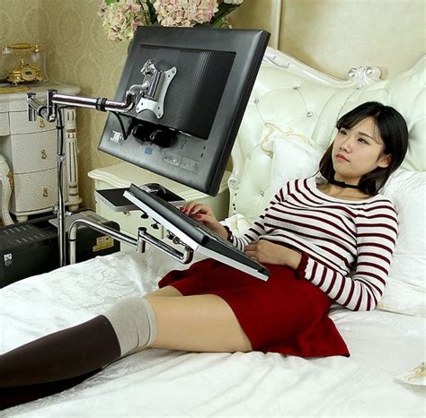
Laptop mounts for use in bed: As seen in figure 1 and 2, these are commercially available but the chances of them being available in India are slim. Another option is a trolley mount ipad stand, but we want something to hold laptops. Another wonderful and apt example is as shown in the video here.
As a conclusion, it seems a proper robust over the head or from floor to bed size adjustable arm is necessary. This essentially has to be a low cost device as compared to the imported devices listed above.
Engineering/design ambitions
Ability to hold up to 5 kg (laptops weight ~3kg).
Long arms – should be able to reach from floor to serve a person lying in bed.
Low vibrations when the laptop is typed onto.
Proper laptop holding fixture for fall-free secure positioning.
The whole jig should be freely moving on the floor so that it can be transported across rooms and can be used beside beds, chairs, tables, etc.
Should have elegant design to fit into a home use.
Ease of adjustment to encourage fine adjustments to suit various needs. Also should be operable by non-trained persons (care-takers) without much effort.
Low cost, so that its accessible across various sections of the society.
Open source design – A design, designed for easy small batch production processes using typical infrastructure found in low-resource settings. This approach is in contrast to exotic machining intensive designs from reputed manufactures of such arms.
Prototype #1
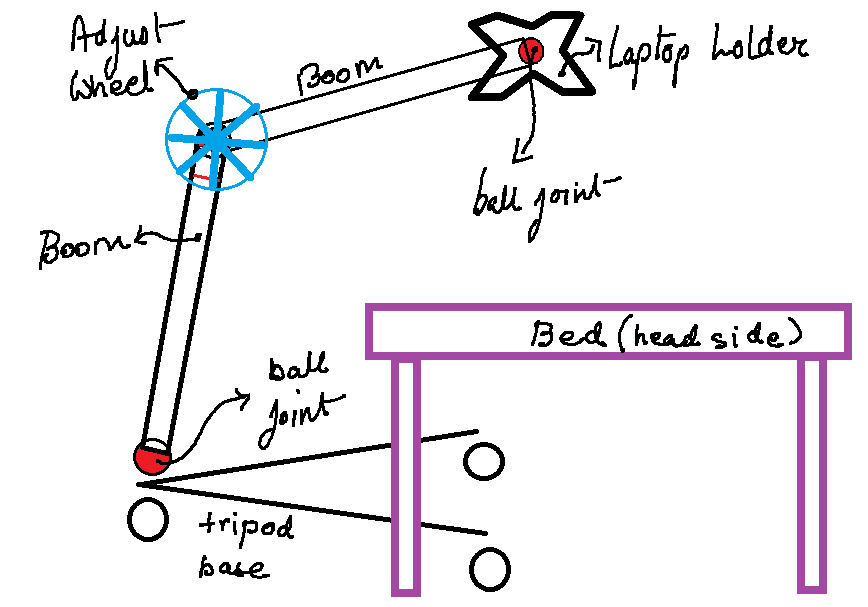
What was proposed originally was a 2 beam device, modeled on the Manfrottos’s Magic arm, but of obvious large size. In the depiction below the base is mounted on trolley wheels for portability.
The challenge was the proper design of necessary friction to lock the ball in position. Designing hinge mechanism with built in friction actuator to fix the ball joints on both opposites of the central hinge was another challenge. A ball with stem was harvested from a Toyota Innova front wheel ball joint.
Arm view
Reasons of failure : The arms flexed quite much, not enough to hold their own weight when in the air. See a video here. Much more friction or tightening grip was needed.
Prototype #2
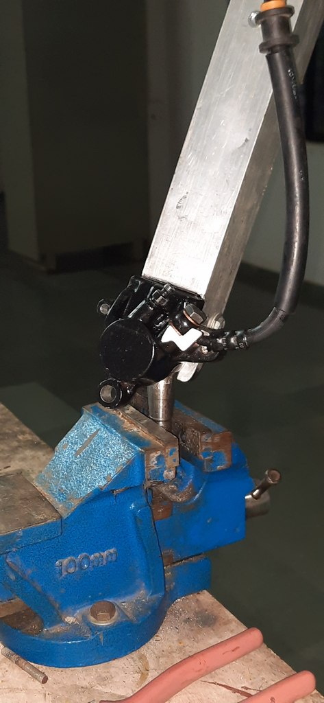
In prototype#2, I used the ideas of hydraulic power to increase friction grip to the ball. The same Toyota Innova ball was used and a bracket clamp to grip the ball was made by hacking the disc brake housing of the common Bajaj Pulsar motorbike. 3 ball joints were used, all connected to a single pump. Once pumped, all 3 ball joints clamped the respective balls, and thus should have fixed the positions in arbitrary space.
Closeup of the hydraulically clamped ball joint
Reasons for failure: The overall structure turned out to be very heavy, the pumping of hydraulic system was cumbersome and it seemed that it worked but not not quite steady. It also seemed this oil can leak, not a very good proposition for a home system.
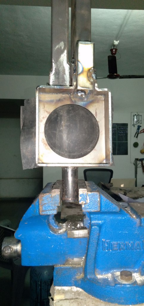
Another ‘pincer ball’ mechanism was attempted, but now with a bigger ball. The balls are commonly found from home decorations, railings of stair cases which are in fashion in the markets of India now. The grip was added with a rubber sheet to increase the friction.
Reasons for failure
Still quite heavy. Despite using strong stock metal, the arms bend when tightened which is not desirable. Bending arms loose on the amount of friction which can be generated on the ball, and the whole thing just tilts on its own weight.
I placed a rubber to increase friction, it helped. but its not enough.
Prototype #4
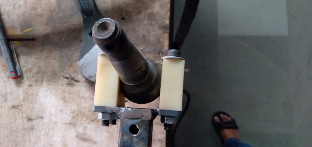
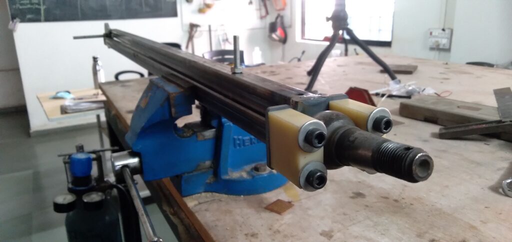
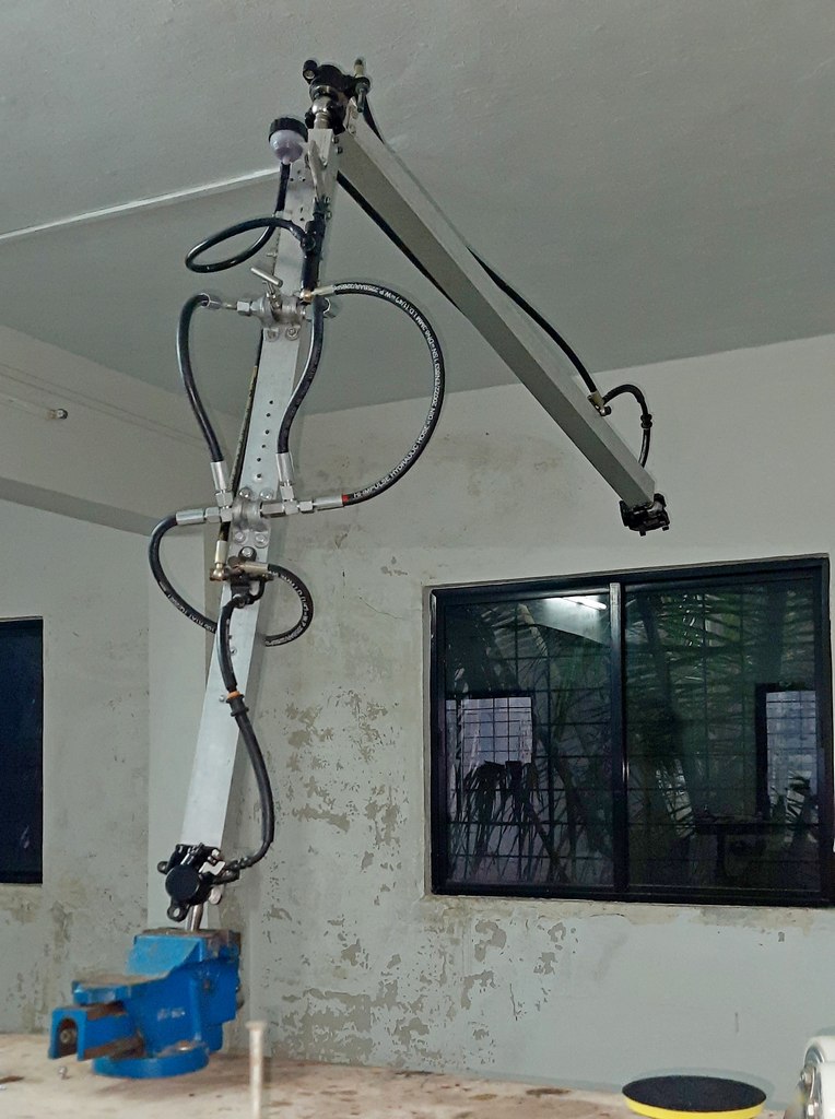
Inspired from the instrumentation articulated arm clip here, I wondered why not enlarge the system? Here’s the number of prototypes I tried. The idea is that there’s a steel cable which passes freely through each ball (there are 2 holes in the ball) and pipe. It is tightened against the length of the system, so that each ball and pipe presses against each other. The resulting friction should lock the components together, with possibility of holding itself in arbitrary shapes and positions.
Reasons for failure: The friction created on the lowermost ball is not enough. It droops under the weight of the overall device. Some better method to increase friction between each ball and pipe is necessary. This method has promise, but only for smaller table top mounts perhaps.
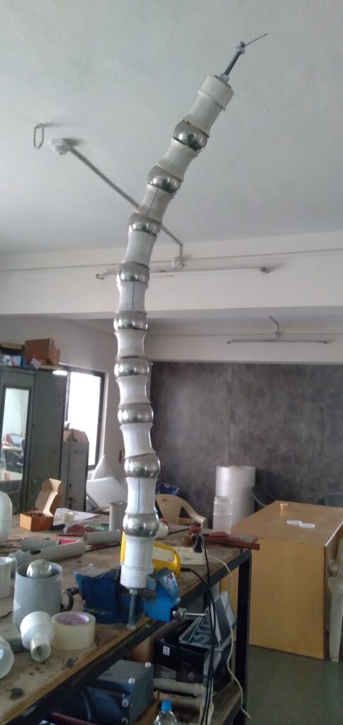
Prototype# 5
It seems frictional locking will need immense amounts of friction, which will not be tenable engineering-wise. One alternative is to have teeth to teeth locking system (like gears) and articulating 1-axis joints instead of ball and socket designs tried so far. This is the conventional engineering way. Another interesting way is perhaps to do away with frictional joints altogether!
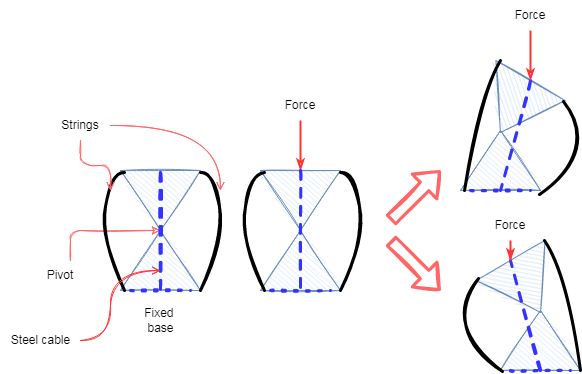
Illustration of a bistable element resulting from a non-stable equilibrium structure.
In the above figure, 2 bodies are illustrated fixed to each other at a pivot point. When there is a cross-stress across the 2 triangles with the pivot point midway between the 2 bases, the triangles may flip on either sides, as shown. There are 2 loose cables on the side, which help fix how much the triangles bend relative to each other. So, another way to put it, instead of creating structures with arbitrary angular positions in between, how about create a “bistable” joint, with only 2 possible states? Imagine a long chain of multiple such triangle pairs, all connected via a central steel cable, the tension of which can be adjusted to result in bistable positions of each element. Thus this chain can be configured in arbitrary configurations!
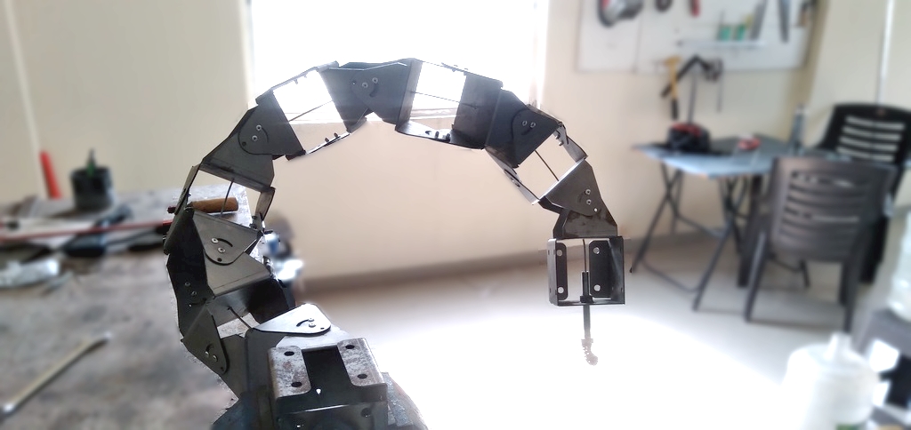
An example of this was somewhat successfully tested in the following prototype. Here multiple discs of a certain shape and wedged into each other, and tentioned by a steel cable. The tension can be adjusted. The images below show a state which could be achieved.
While the idea kind of worked, and seems to be the closest prototype I could achieve towards the target engineering constraints, it was a flimsy design. Many flaws came to light, one being that under slight overstress, the discs would pop off and the whole thing collapsed. Also, it was very difficult to adjust as the friction between each disc was very high, something i foresaw, but still went ahead to make.
In order to make a friction free design of easily “snappable” bistable elements, i resorted to what is called a flexure joint, or in engineering terms – cross-linked flexure pivot joints. Such a structure has bending movements only along a certain axis and is significantly rigid on all other axes.
However, I realized that while the pivot position is virtually fixed, it in practice moves with the rotation, thereby resulting in the tentioned string method of adding compressive strength as non relevant here. Since I could not stress the elements in other way, this design failed.
Conclusion
Many prototypes have been tried, with various minor successes but major failures. However, I have come to a better understanding of the challenges involved. Hope it works in the next few attempts.