Many people including myself are or were involved in making low-cost ventilators in reaction to the panic need expressed by the leaders during the COVID19 crisis. Most of us began working on the MIT E-Vent model (discussed in 2010 paper here) that uses a bag-valve mask (BVM) normally available with all emergency care professionals, in all countries, as a fundamental piece to begin building the ventilator on. There are many advantages to this approach such as availability, low cost, non interference with medical grade materials issues, and others. Many people made these devices, focusing on the mechanical part and there may be many reviews out there.
I am associated with such a team of engineers at the College of Engineering, Pune, under Prof. Sandeep Anasane of Production Department. In 2 weeks time when i began working with Swapnil, Abhijeet, Kaustubh and Dr. Anasane, we made about 3-4 different designs. Two have lasted the test of time of which i am free to present my model that uses a commonly available Maruti Swift wiper motor, a hall sensor+magnet combination to convert it into a servo, a motor driver and some Arduino Nano to complete it all. Here’s a video.
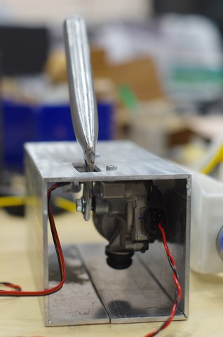
A very simple design. 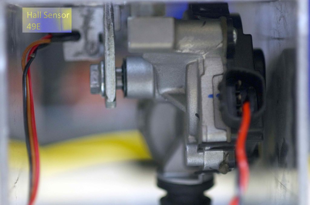
Analog Hall Sensor 49E 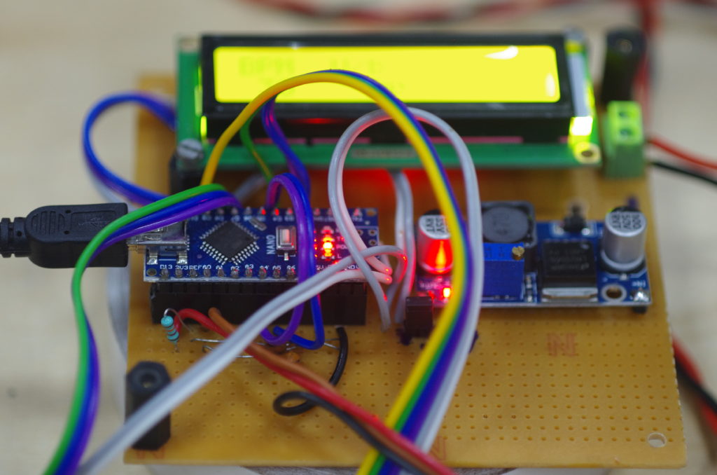
Arduino Nano controls
The other one is developed by the team as a whole where the sharing policy is not very clear so i must refrain from sharing.
However, what struck me as we progressed over making these prototypes is that the electronics part is hugely underestimated. In the 2 weeks time i learnt a significant amount of things about ventilation and its pitfalls such as ventilator induced trauma. The latter part is the common side effect of such devices that assist in such difficult times. I have now realized that all this is not simple. Along with advanced ventilators it is mandatory to have specialists and experienced doctors around to manage that device. In wrong or untrained hands it can kill.
Point being, the idea that amateurs like ourselves could come up with impactful solutions to the ventilator end of the COVID19 problem spectrum seems to me a pure fantasy.
Yet, although i have given up on this end, here is a hack that i discovered that could be still used by optimistic ventilator designers elsewhere.
Electronics for basic flow measurement and respiratory pressure
Often many designs are focusing on the mechanical pressurized air delivery with intermittent strokes that are adjustable as per the attending nurse/doc’s understanding of the situation. What is missing are 2 key realtime feedback mechanisms that in my naive opinion are an absolute must:
- Air flow measurement to figure out volume of air delivered/breath as well as the rate at which air is pumped.
- Respiratory pressure measurement that indicates how the patient is experiencing the ventilation.
Both these need pressure sensors. When we began this aspect of the work at CoEP, we could not find the right sensors. In the regular city shops, other city teams working on ventilators had exhausted all the options. We had a few in stock to begin with. There was even not much clarity within the team as to what is the ideal sensor required?
What pressures are we talking about?
- Respiratory pressure measurement: 0-60 cmH2O = 0-5.88 kPa.
- Volume flow orifice pressure range – 0-0.3 kPa
What we instead got were these sensors with some key properties in the following table.
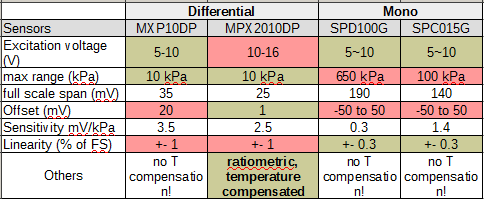
The greens indicate good match, the reds don’t. What i found was that only MPX2010DP was the closest that we could get, atleast on the respiratory range. It was also a ratiometric sensor (so we needn’t worry about excitation voltage fluctuations) as well as temperature compensated! The latter is always good, so MPX10DP is dropped. In fact the MPX2010DP datasheet does mention its use in respiratory diagnostics! All this we discovered (thanks to Swapnil who called the shops to check what they had) after we were stuck with a few samples of MPX2010DP at Rajiv Electronics, the local electronics store. Each MPX2010DP costed about 1200 Rs.
Respiratory pressure measurement could be easy with a differential sensors and as simple as connecting the positive port of MPX2010DP directly to the inhale/exhaling mouth piece on the patient’s mouth, the other end to atmosphere. However we need another piece of critical equipment to measure volume flow rate – an orifice flow sensor. Thanks to Kaustubh’s ingenuinity and research this part was readily available and used in commercial ventilators such as made by GE – the SpiroQuant H flow sensor by Envitech, a Honeywell company.
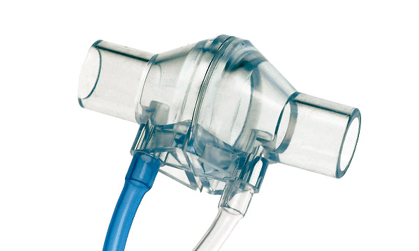
The way this thing works is there is a thin flexible flap in the middle of this piece that restricts the flow by opening or closing as per flow. This restriction causes a pressure difference between the two ends of the device and this pressure difference can be converted into flow rate through the formula mentioned in SpiroQuant H’s datasheet (link above). Simple!
So whats the problem? All is plain and simple!
As you may have noticed is that the output of these pressure sensors is in milli volts (mV). Also these pressure sensors have a full range of 10 kPa whereas our requirements are on 6kPa for breathing pressure and a whopping 0.3 kPa for the flow measurement! So what we need is an amplifier. Kaustubh worked with the common 3 Op-Amp design but unfortunately could not make it working to satisfactory ends. Another commonly available the excellent ADS1115 was used, but again its gain (max 16x) and resolution (16bits) was not sufficient.
Enter the hack! From my experience in designing ADC boards for the SmallDAC opensource controllers, i knew that these pressure sensors are similar to load cells that use a Wheatstone bridge as their basic sensing element, with resistors flexing or contracting and the difference between the 2 bridge arms basically forming the output voltage linear with the pressure or weight. A common loadcell amplifier is the HX711, amply used by hobbyists anytime a loadcell comes into the equation. It has an inbuilt whopping 128x gain and a 24-bit resolution – perfect for our job. Its unconventional and i could not find any case where a pressure sensor was interfaced with this 100 INR ‘toy’ module. So despite revolt from team members claiming that it wont work i went ahead, while others may have been cursing me that i am distracting from the team’s focus areas and spending time in fancy exploits. I was glad it paid off, else i could have been thrown out!
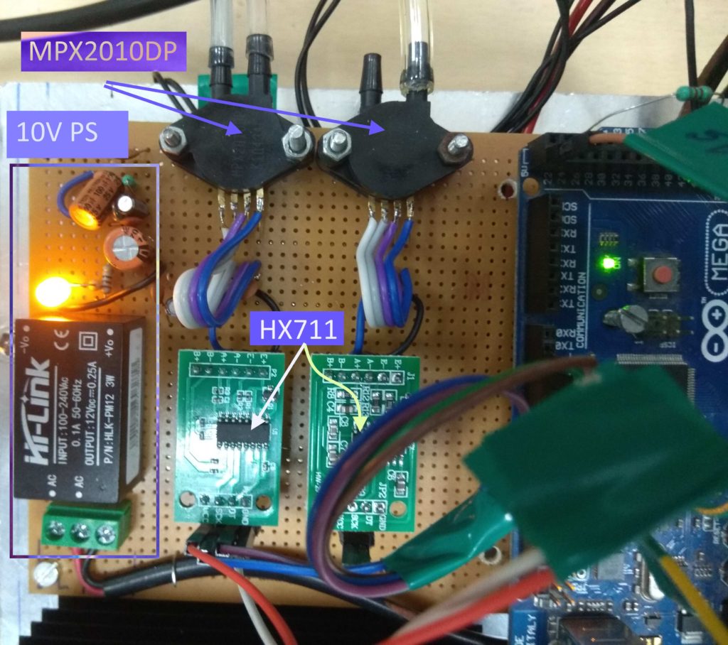
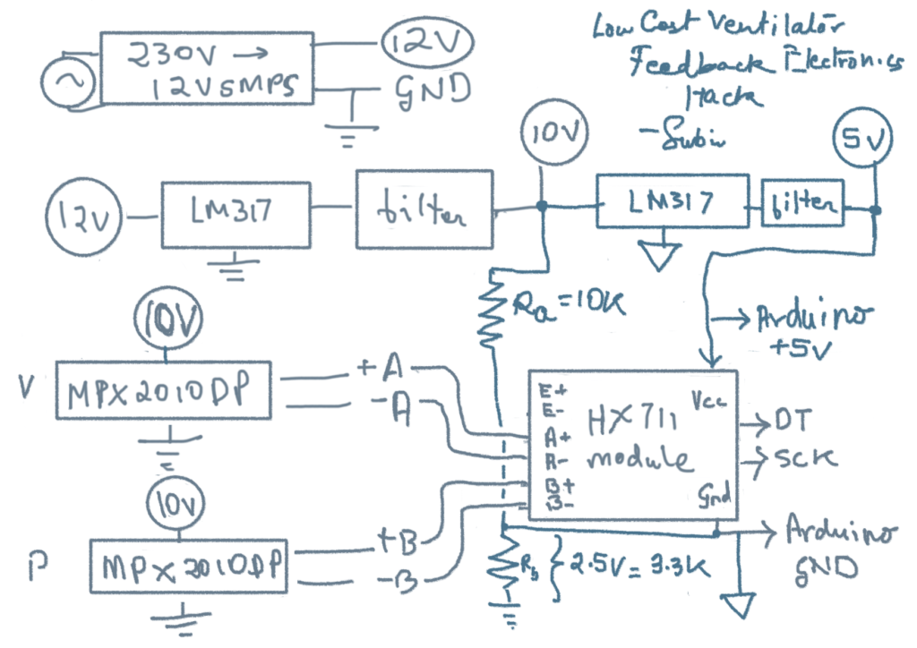
The circuit is a bit to be noted. These MPX2010DP require a 10V supply to be excited. So i had to create a separate 10V supply (left of the above image) using a 230V-12V PCB mounted SMPS that i could get from Rajiv Electronics (~350 Rs). Then i used a LM317 (i know dropout is 3V, but thats at peak current draw!) to reduce to a clean 10V supply.
The way these bridge sensors work is that their output is centered around half of the supply voltages = 5V. Now HX711 is a 5V device, so the trick i used here is to not connect the 10V supply ground with HX711’s ground and instead only connect the differential output of MPX2010DP to the modules A+ and A- ports. Thus the module is experiencing directly the difference without the 5V bias of the 10V exited pressure sensor. Maybe there are other ways of solving this bias problem, but i must learn more about these kinds of issues.
The output of the module was connected to a regular digital pin of an Arduino Mega board that also handled the motor works and overall controls. This pressure sensing rig was so sensible that even a touch on an ambu bag was recorded as a nice clean peak while the overall noise was pretty low. I must admit that i had to use a lot of capacitors and tricks to get the noise low, but it worked. I used 2 HX711 modules to interface the volumetric measurements (left sensor) and the respiratory measurements.
Hack update
Well, here’s what can be done to make the above better!
Only a single HX711 is used because it has 2 differential ports A and B. A, which as the max possible gain of 128 (equivalent to a span of +/-20mV) can be used to measure the 0.3 kPa max pressure swings of the orifice flow meter as before. However, port B has a gain of only 32x (equivalent to a span of +/- 80mV) which can be used to access the 60cmH2O or 6kPa range required for measuring respiratory pressure. The 24 bits can be enough to distinguish both these measurements to sufficient accuracy.
The other hack has been to use the same 10V supply to also power the HX711. Now we know the HX711 is a 5V device and that the pressure sensors are outputting their differential signals centered around 5V. So what the above circuit does is biases the ground of HX711 w.r.t. the 10V power supply ground using a Rb resistor. The same 10V supply can now be down moded to bring about 5V supply, referenced wrt HX711 ground. Now this part is a bit confusing to me so the values may change or maybe my scheme is wrong? Need to check/think…
The code side could be any that uses the standard HX711 library. Try the simpler ones that do not hide the inner workings, these are much easier to modify!
Happy hacking 🙂