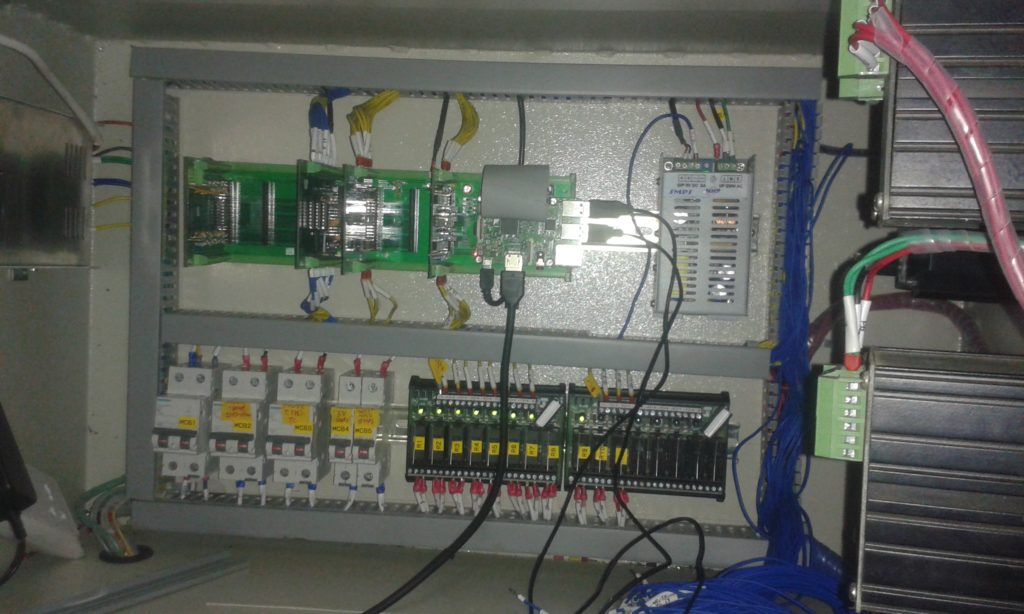
The SmallDAq V2 was integrated with an industrial control panel which will monitor and control a jaggery unit designed and developed by our client Prof. V. Sardeshpande.
Here is the LCD monitor that displays all the process and gives access to the used to control various valves and pumps just by using mouse clicks. This frontend GUI and its backend python codes were all developed inhouse. PyQT5 was used for the GUI and www.draw.io for making the process illustration.
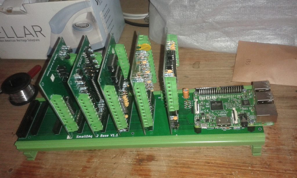
An inside view. Note the SmallDAq V2 (the green PCB thing). More cards and wiring will be added, hence the open wires on the right.
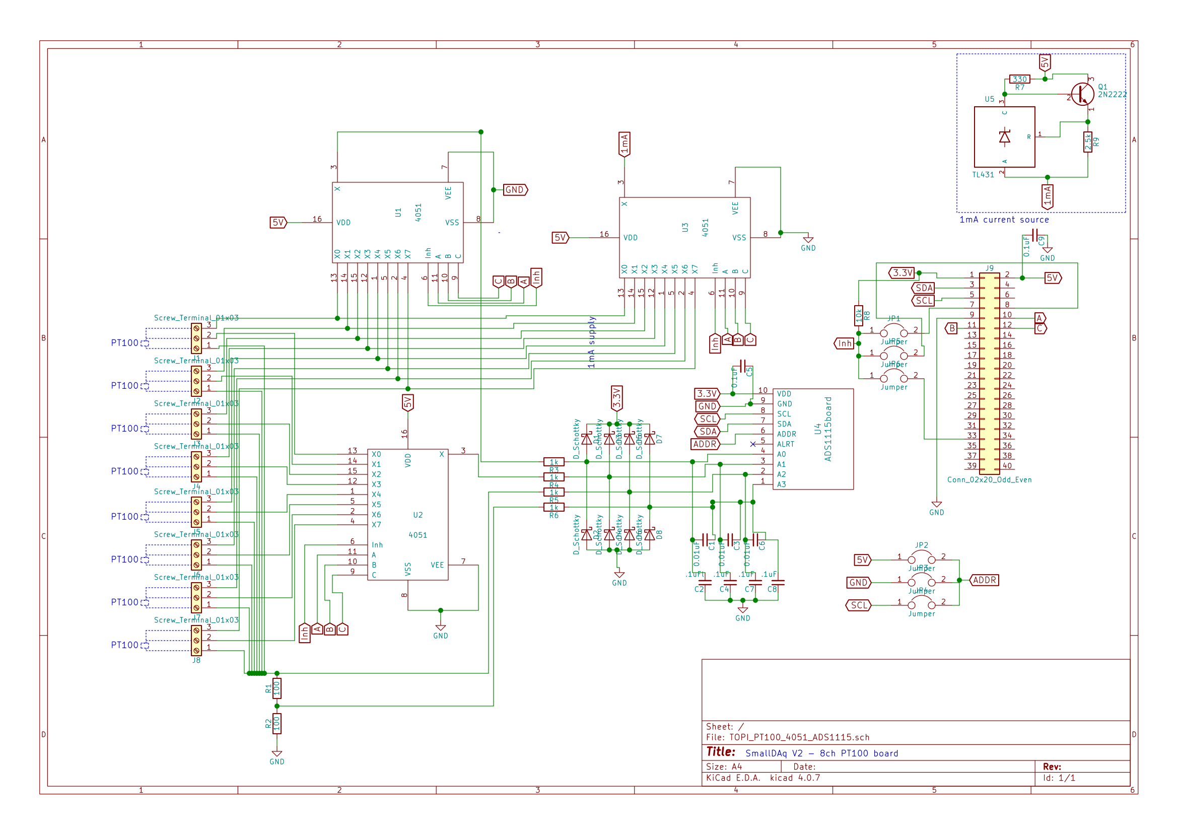
I went through various designs, searched a lot over the internet but only found few references. Main question was – can the HC4051 be the right choice as a multiplexer. Also if TL431 will give stable current. The always helpful online community at Stack Exchange helped me immensely and directly. Here is my post and discussion over there. I modified the solutions and here is the currently adopted one. Designed in KiCAD.
So the way it goes is:
A single TL431 (right top corner) supplies 1mA.
This 1 mA is multiplexed by a 4051 – U3 on the schematic to the 8 PT100s. Since its a constant current source, the on resistance (Ron) of 4051 would not matter or change anything.
I need to measure the input voltages of the 1st wire of the 3-wire (starting from top to bottom) PT100s. So another 4051 – U1 does that. Here, since i am only measuring the voltage using a high impedance ADS1115 (6 MOhm i read somewhere) there is no current flowing through the 4051 so no voltage drop, hence Ron is not important here too.
Then the monitored 1mA current passes through the PT100 1st wire and can be sensed by the 2nd wire using another 4051. Again since there is no current passing due to high impedance inputs of ADS1115, no potential drop across Ron of 4015 is expected. The difference between the previous measurement (point 3) and this one gives me the potential drop across the wire for a constant current flow = wire resistance!
Finally the 1mA passes through the PT100 and emerges onto a series of 100 ohm resistances. The potential drop across the top 100 ohm resistance is measured again. Since this 100 ohm resistance is 1% accuracy i can compute the current passing through accurately enough. So variations in the current source (TL431) can now be neglected. This also makes the whole thing ratiometric, as explained below.
I didnt want to short the 4rth measurement terminal of the ADS1115 to the ground because of a fear that it would lead to ground loops. So i put in a 100 ohm resistor there. I am purely guessing over here. Maybe a higher resistance must be used than 100 ohm, but that should not overload the TL431 supply.
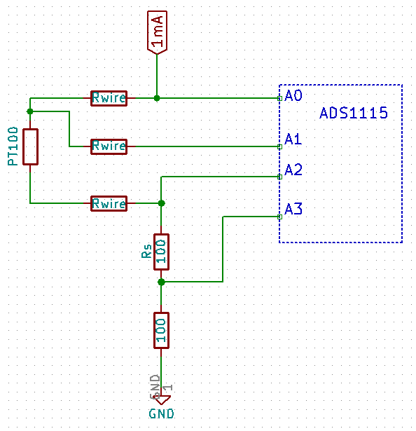
So how does one measure the PT100 after all the above steps? The above schematic is simplified here where a single PT100 interfaces the ADS1115. Note that Rwire is the resistance due to long PT100 wires and is an inherent part of the PT100. The ADS1115 has 4 analog inputs and has a special mode in which each of the 1st three – A0, A1, A2 can be measured differentially with A3. This is what we will use.
PT100 – ADS1115 interface for ratiometric measurement.
First we must measure the circuit excitation current $I_{ex}$ flowing through the circuit:
$R_s$ is a known value, in this cas of 100 $\ohm$. Secondly, the $R_{wire}$ can be deduced using following equation. Note that $I_{ex}$ is not passing through $R_{wire}$ of the wire leading to the A1 pin because A1 is high impedance.
Further, the relation between the voltages at A1 and A2 and the Pt100 can be put as:
\begin{equation} \label{eq:RwirePt100}
R_{wire} + R_{PT100} = \frac{V_{A_1-A_3} – V_{A2-A3}}{I_{ex}}
\end{equation}
Using eq.\ref{eq:Iex} and eq.\ref{eq:Rwire} in eq. \ref{eq:RwirePt100}, a simplified form emerges:
So far it works. Need to check this in the full range of 0-200 $\deg$C.
The circuit above has additional components to protect the inputs of ADS1115 as well as filter the input. The filter values have been shamelessly copied from other sources which im stupid enough to not remember or note anywhere, sorry.
Like SmallDAq V1, there is a growing need among scientific and student communities of a low cost data logging system with controller and human interface features. With the advent of low cost electronics, opensource systems and internet communities its now possible and obvious that such Data Acquisition systems are made available. Hence the SmallDAq V2.
Its features are:
Modular construction – features could be added or subtracted by using different cards as per needed by the user.
Raspberry Pi 3 B as the base computer.
Human interface and interaction ready with any LCD screen with HDMI port and coupled with mouse and a keyboard.
A 30cm long base board that holds the RPi and seven 2×20 pin ports for adding cards. An IDC cable connects the RPi to the board. Another IDC port available for further expansion. The board can be mounted on DIN rails.