RainCloud V0.4

After a few variations (V0.1-V0.3) finally a small version was developed to reduce cost of acrylic cutting and overall dimensions.

Side view
Top view.

It has a small spihon built into the various layers, as seen in the cross-section below.

Crossection of the disc type rain measurement device.

Its again designed to drain at about 1mm of rain fall. Fitting is the same as previously done.

Rain collector end of the device.
The disc group just sits inside the reducer snugly, resting against a small step pre-built into the reducer.
Extended teflon tube protrudes out from bottom. Shown here in upside-down condition.
Another bottom view.
A 3D rendering of PCB and components for live transmission of rain data.

RainCloud V0.1

Initial idea was to create a device which anyone could make. However, after many jugaad tries it was clear that if volunteers make rain gauges, each will have some difference than the other in terms of accuracy and so there will be no way of relying on the data.

So, reluctantly i chose to remove the uncertainty in the design by using a laser cut acrylic design.  It is designed to drain with every 1mm of rainfall, i.e. that is the least count.
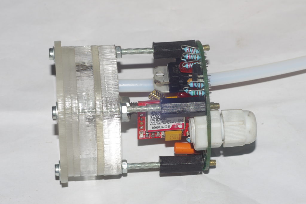
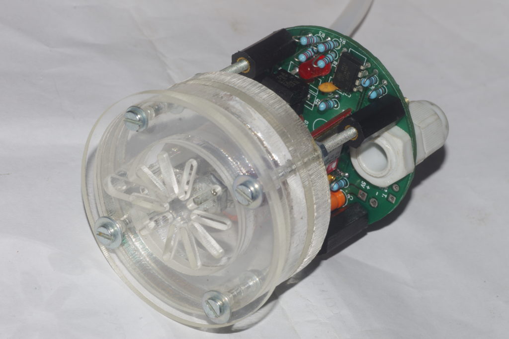
Here are some pics.

3 plate acrylic design. Receiver of rain is on the top side. It fills a tank on the left. The tank fills only upto where the upward pipe bends down. Thereafter, water auto-drains through the bottom. Two wires for the two electrodes for sensing a draining event.
It fits onto a commonly available PVC pipe reducer. A PVC pipe (in background) fits and seals the device completely. The opening rain collector diameter of the reducer is 110mm and the pipe diameter is 63mm. The ratio of volume of rain water collected in the acrylic tank system (just before draining) and the rain collector area is the rainfall measurement, in this case = 1 mm.
Another view of the system. Note the collector design.


Intro and idea

Why?

Maybe there’s not as much need as i perceive it, but as per my discussions with my friends Mrs. Pallavi and Prabhu it was clear that there are far few of rain data points available. Here are some of my perceptions (which one is free to check and prove otherwise) :

  • India’s IMD has a network but i suppose they report the data only at the end of a day or say every half a day. So data rate is too low to make a live map.
  • IMD network’s density is low. As per Prabhu (my friend from MSc days and currently at one of CDAC’s project leaders in Pune), the state of Sikkim has only one IMD sensor!! Similarly, the vast landscape with many terrain features make rain fall a very region specific thing, so rain data must be of higher geographic density than currently is the case.
  • Rain data is not available to the public for independent and parallel processing. It has to be received through IMD and one can only guess the difficult bureaucratic path. As discussed with Mr. Mayuresh Prabhune, an active citizen science torch bearer in Pune, one has to struggle for getting data from public funded institutions.


RainCloud

So the plan is to create such a system with following features:

  • Live streaming of rain fall data every 30 minutes, 24×7.
  • Live data plotted on an online geographic map, accessible to anyone, free of cost.
  • Data could be downloaded by anyone for further analysis, free of cost.
  • Cost of device should be low so that density could be increased. Also device should have long maintenance free life.


How to do it? – the science and engineering

The main issue with conventional rain guages that have online data reporting capability is the need of calibration. So if ours is to be better, then one must remove any moving parts from the design. So how to make a device that makes a measurement of rain and then empties itself without any moving par like valves, etc? – Enter the auto-siphon.

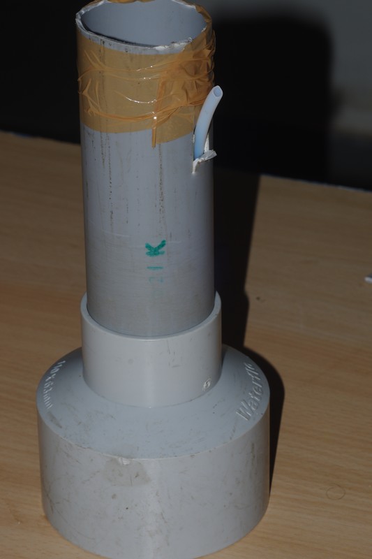
If you take a pipe (a PVC pipe in the following images) and a bendable straw (i used one from a TuttiFrutti mango drink), as seen in the images one make an auto-siphon.

Top view.
Side view

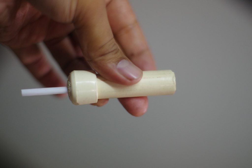
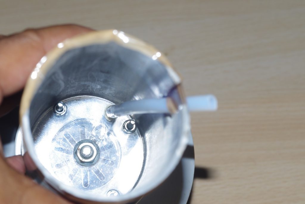
The white straw is sealed by the small hole (as compared to its own diameter) made in the PVC cap. When this piece is filled with water upto the level of the bend (1st image) then it auto-drains completely.

Conclusion: An auto-siphon designed in such a way as to drain everytime a fixed amount of rain has fallen.

So how to do the measurement?

  1. Every time a draining event happens, the water passes over two electrodes separated normally by an insulating air gap.
  2. One of the electrode is at a higher potential (5V) as compared to the other, so when water passes over (during draining) the second electrode gets a current from the first one.
  3. This is detected by a microcontroller as a digital signal and a counter is incremented. Thus each count signifies a predetermined amount of rain volume being emptied.
  4. The change in count per hour then corresponds to the rain rate/hour.
  5. The latest count value is transmitted by the microcontroller and associated GSM/GPRS circuit to a website.