Sanitary Napkin incinerator V3 status

(The following post was optimistic when it was first posted in September 2017. Since then a few things changed as has been strike through here.)

This innovation is undergoing an Indian patent process initiated by our client Vigyan Ashram. Hence Small Design can not blog/discuss about it. Once the patent is secured, Small Design will make public all the related documents. UPDATE : Vigyan Ashram disagrees with me sharing my innovation as it claims full ownership.

  1. Although I am the main innovator for this design, i am personally against patenting a socially relevant project like this one. However, the client Vigyan Ashram has the final say in this regard. I have chosen to exclude myself from the patenting process.
  2. VA has promised me that the patent initiative’s sole objective is to reserve the credit of this innovation with themselves. This will help them with funding agencies that support science and technology projects in India. According to their written promise, this innovation will be ‘open-sourced’ once patent process is complete: meaning anyone can copy, modify and produce this innovation by giving name credits to VA. Sadly this is not true anymore on behalf of VA.


When i get some time off i will try to create an opensource version of the incinerator. – 7th June 2018

V1: Serious design issues

More testings were done on the repaired V1. However following serious observations could be made:

  • Auto-thermal operation has not yet been achieved. The flames occur as interpreted by significant rise in flue gas temperatures even when the heater is switched off by the PID control. However the flames do not sustain and the heater is required to be fired up. This process occurs every 1000 seconds of operation.
  • Due to operation through natural draft, significant amount of heat is lost in the pre-pyrolysis stages due to continuous air convection.
  • Due to the straight and simple geometry, the flames of pyrolysis gases and vapors do not reside for a long time in the system, not enough to transfer sufficient heat to the waste chamber. This again calls for firing the heater.
  • Pyrolysis and consequently the flames arise only when the heater is on for sufficiently long time. Even when the temperatures at the exit are the required > 270C, there are seldom smoke signs of flaming.
  • When i tested with child diapers that have a lot of water content, 1 hour is simply not sufficient for 2 diapers. Infact its been observed that a sufficient drying stage is mandatory or else the following case occurs: The drying of top regions is not complete and continues while the pyrolysis of bottom content produces pysolysis fumes. The net gas outflow is not fuel rich and since it has H2O content its too hard to reach and sustain a flame at the gas exit due to the heat capacity of moisture. Thus, the highly toxic white smoke.
  • There is no way to know as of the current model as to when the contents of the waste chamber have been completely charred. A pre-fixed time of process works only for a known number of sanitary pads, for example 1 hour of process from start to finish is good for 5-7 pads at max, ½ hour is good for 2-3 pads and so on. Chamber capacity being 15 pads this can not be predetermined. An algorithm or technique to determine when pyrolysis is no longer occuring even when temperatures are alright is being developed.
  • Even with all the above observations taken into account, im not able to set a proper PID loop that can work efficiently. I have significant overshoots and undershoots resulting in bad operation : white smoke, black smoke when overheated, wastage of time, no definition of whats actually going on.

V1: Issues

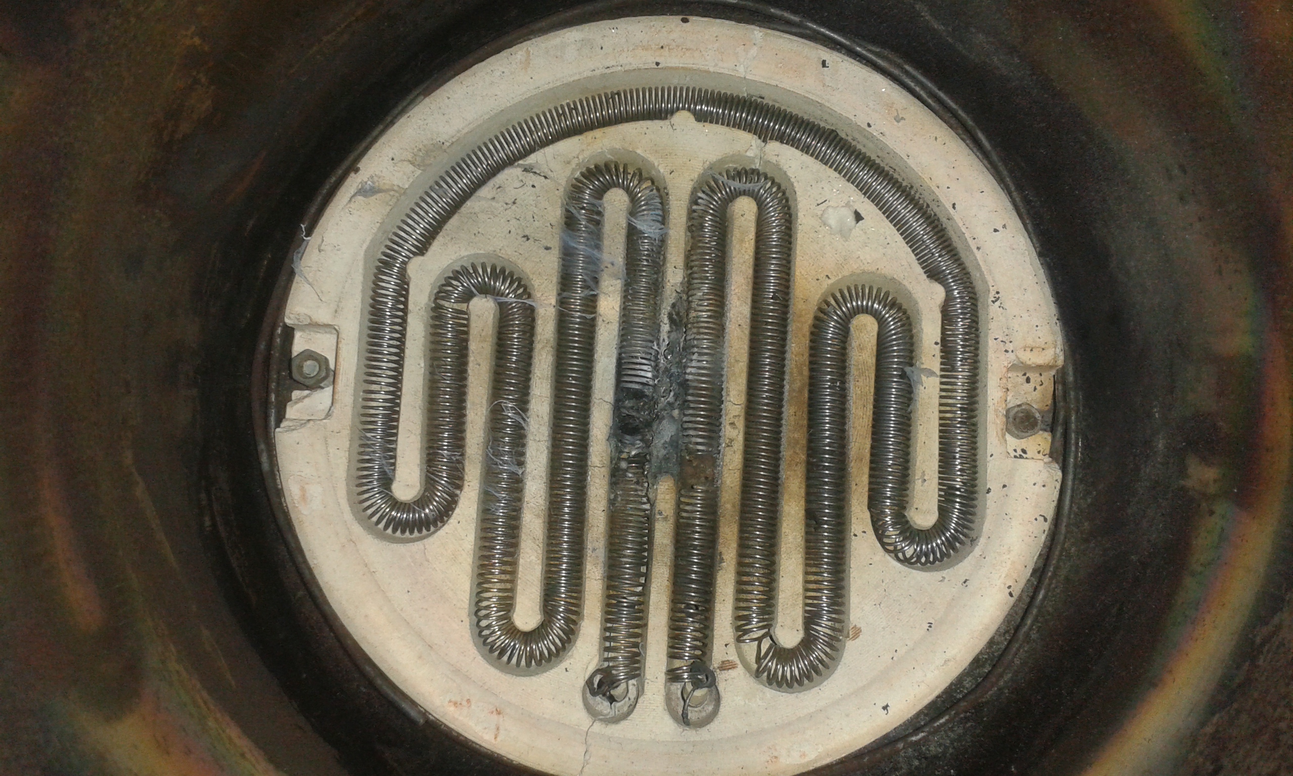
When V1 was brought back to Small Design after the first user trials, the main challenge was how to prevent the coil from getting damaged. Once opened here’s how the burnt coil looked:

Two issues were observed:

  1. The coil was burnt in the center where the gases exit the waste chamber.  This implies that the significant heat of the flames reaches higher than 1000C of the coil limit burning it out.
  2. Copper wires were used to connect the nichrome coil to the outside. The copper was structurally fine but the contact was broken due to oxidation at the surface of the copper.


Solutions:

  1. A 2mm plate was placed on the coil that would protect the coil from direct flame. It works so the coil is no more damaged.
  2. The nichrome wire was salvaged and extended on both the ends to a long wire leads. These leads were insulated with ceramic beads and led directly to interface with the mains neutral and the SSR respectively. This solved issues with bad connectivity.


V1: First end-user trials at VA Girl’s hostel

  • Device was big so could not be accommodated into the intended are of a conventional bathroom.
  • Arduino was set to operate cycle for 1 hour.
  • In first trial, 12 used napkins were kept in the waste chamber.
  • In the first cycle of 1 hour, the waste content was not completely incinerated.
  • Some smoke was observed and smoke smell was irritating.
  • A second cycle was done with the same semi-decomposed contents.
  • In the second run some sparking noise was heard sometime half-way into the cycle.
  • The device was switched off after the apparent completion of the cycle and contents were found to be satisfactorily converted into ash.
  • When i went there to take another trial in front of myself it was observed that the fuse was blown in the second trial, which was replaced. Further trying revealed that the coil was also disconnected.


Conclusion: V1 worked but A) coil did not last B) It took more than 1 run to completely burn the napkins. C) Smoke was observed.

Low smoke Sanitary Napkin Incinerator V1 – base information

( Developed at Small Design, Pune India. Development partly funded and supported by Vigyan Ashram, Pabal, India)

Abstract

A novel incineration device has been developed that uses a separate pyrolysis stage to decompose used sanitary napkins into hydrocarbon vapors and combustible gases along with some non-combustible gases and char. These vapors and gases are made to pass over a high temperature zone, created by electric coils (>500 degC) where they autoignite in the presence of oxygen. The heat from the flames partially drives the pyrolysis of remaining sanitary pads. A smoke stack thermocouple sensor feeds back values to a PID controller implemented through a microcontroller to maintain proper pyrolysis and combustion conditions. At the current stage of development visible smoke has been reduced drastically compared to conventional small incinerators. Further studies in flue gas composition, combustion efficiency, etc are to be carried out.

Background

Sanitary napkin incinerators are widely available and can also be bought online in India (eg.). The products range from sizes suitable for personal home use to large sizes for use in institutions, hotels, offices, etc. These consist of an insulated chamber within which there is an electric coil. The sanitary pads are dropped into a chamber which is heated to high temperatures in the presence of forced or natural air draft. The high temperatures ignite the sanitary pads (which are made of polymers materials) and the fumes are carried out of the setup through a chimney.

The problem here is that the designs often do not ensure that the fumes from the sanitary pads catch fire and large pockets of unburnt hydrocarbon (from the polymers) gases are emitted as white smoke. Proper combustion requires three things: Right temperature, proper fuel and oxygen mixture (near stoichiometric or lean) and time for combustion reactions to complete. The existing designs fail to stop generate smoke during the following conditions:

  1. The sanitary napkins essentially contain bodily fluids and hence are contain water. If a direct flame is exposed to such a water soaked material, the surfaces immediate to the heat source will dry first, pyrolyse and if temperatures are right, catch fire. This is turn will dry the underlying material. However, pyrolysis begins non uniformly whereas due to the presence of water the temperatures near these surfaces are too low to allow combustion reactions to occur. As a consequence some pyrolysis vapors and gases escape as visible white smoke even if surrounding areas are in flames.
  2. Even with a forced draft which ensures presence of sufficient oxygen, the current product designs do not ensure that every parcel of gas in the chamber while on the way out to the chimney passes through high temperatures (at least above autoignition temperatures) AND has the right fuel-oxygen mixture, thus resulting in smoke. The smoke from such incomplete combustion is mostly white or brown in color and may contain high amounts poisonous carbon monoxide and toxic hydrocarbons such as furans and dioxins. Although the chimney helps transport the gases away from end users, it nevertheless pollutes the environment and may also affect nearby rooms or people living/working around the incinerator area.

The necessary way

To improve the above issues in the existing designs, the following process is being developed:

  1. A drying stage needs to be implemented where the temperatures are near 120-200 deg C in the chamber containing the sanitary napkins. Note that pyrolysis reactions start above 300 deg C.
  2. After sufficient drying, pyrolysis temperatures of above 300 deg C need to be achieved in the chamber. The exiting pyrolysis fumes would then contain various amounts of water vapor, CO2, CO, and various hydrocarbons along with fumes of degrading bodily fluids (proteins) (refs).
  3. These gases and vapors must pass over a high temperature zone above the autoignition where they combine with air inflow to develop flames.
  4. The heat released from such flames must be able to drive the pyrolysis and sustain the process till the complete charring of sanitary napkins within the chamber.

These process are combined into a compact thermally insulated product which is controlled by a microcontroller system.

Implementation

A cross section of the prototype that attempts to implement the above process is shown in the Figure 1 below. There are three chambers contained within each other made up of stainless steel jars redily available in the Indian market as containers to store food items in the kitchens of almost every household. The inner most ‘Waste’ chamber holds the sanitary napkins and is made air tight using a thermally insulated lid. Once this lid is closed there is only one exit termed ‘Pyrolysis gas exit’ in Fig 1. Beneath this waste chamber is a 1 kW electric heater that is controlled on/off by a microprocessor using a PID algorithm (details in electronics section). The electric coil and waste chamber are themselves contained in an insulated chamber named ‘Flame chamber’ in the figure. This flame chamber has an inlet of fresh air beneath the electric heater coil and an exit of combusted flue gases through a chimney. The gas current operates through a natural draft. A thermocouple measures the flue gas temperature at the base of the chimney which forms the feedback to the PID loop.

When the electric coil heats the waste chamber, at around 120-150 deg C, drying of the waste takes place. This stage lasts about 10-20 minutes depending on the waste chamber loading. After this stage, the temperature setpoint of the flue gases is increased to 270 deg C. Pyrolysis gases emerge through the gas exit of the waste chamber and pass over the red hot coils. Air from the air inlet (at the bottom of the device) is also present in this region leading to formation of a flame. The temperatures of the flame are around 800-1000 deg C. The flame partly heats the waste chamber while exiting through the chimney. A temperature of 270 +/- 10 was found empirically to produce a visibly transparent flue gas.

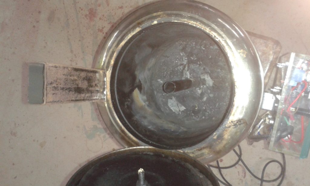
Figure 2 shows the prototype in reality constructed out of SS containers. Figure 3 shows the waste chamber insides and the exit tube.

Electronics

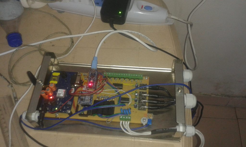
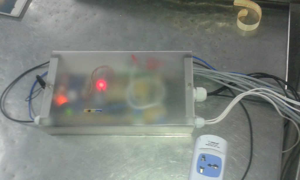
The electronics is composed of a Arduino Nano microcontroller board that drives a Solid State Relay (SSR) on and off to which is attached the 1 kW electric coil. A thermocouple (k-type) is placed at the base of the chimney to sense the temperature of the flue gases. A readymade PID library developed for Arduino is used. Tuning parameters of the PID are yet to be fine tuned to get a foolproof process.
How i repaired a Pentax SMC Takumar 400/5.6

The main things used were
  1. a lens ring removal tool
  2. a small air blower
  3. simple air wax removal ‘q-tips’
  4. normal hand gloves
  5. 10% hydrogen peroxide
  6. simple nivea cold cream
  7. some lens cleaning paper
  8. some brain and a lens to clean (no particular order)

So here was a cheap (40 euro) lens from ebay posted from Japan. All seemed to be in first class condition except that the lens was infested with fungus and hence so cheap ( i love to play with high tech and undervalued stuff trying to discover their true potential or value)

As seen in the following image, the fungus was too much.

on the inner elements too!

So i opened them up here. its not clear in the image but i wanted to show how fungus looks like.

Since i could not hold the long lens any other way i held it in between my legs. I covered the lens element with a simple kitchen paper folded many times to provide some protection to scratches while opening the lens. Thereafter i used the adjustable ‘lens opener’ (sorry i dont know the right word for this, suggestions welcome)

Here is the first element that comes out. however i could not manage to seperate the element you see from the rest of the conical body by any amount of vegetarian force.

This is how it looks after the first element came of. 

And here is the fungus on the inner element. Pretty scary to many people who talk about fungus ‘eating’ into the lens coating, but for mortals like me, i would say, its ok i can manage with some loss of contrast and brightness if the coating is gone after cleaning the fungus.

More pieces come of. Ask me to explain how to open or specific questions becasue im very lazy to write all stuff i know, now 😉

Here is the important part. Take a q-tip and take some coldcream onto it and spear it on the fungus infested elements. Please remember that do this only on the elements infested with fungus with the sole purpose of removing the fungus. this procedure needs to be preceeded with cleaning with Hydrigen peroxied that KILLs the fungus. Keep the element dipped in hydrigen peroxide as a first step for an hour or so. only then smear the cold creame and then again keep for long long time. i ket it overnight becasue i had no time. The reason you want to do it only to the elements that need to be fungus cleaned is that removing the cream and associated oils is a tough job and may damage the coatings.

To clean, i used first a mild soap wash in the basin while rubbing gently with fingers. be very gentle, as i can gaurantee that the coatings will be affected otherwise. sometimes one can use only alcohol and lens cleaning paper to do the job instead of washing, though i never tried this (i will try next time with another lens). 
Once cleaned, its really difficult to get the cleaning marks off the elements. this step is laborious and i still have to learn how to do it affectively. Putting back was easy thought it took some time to figure out the right positions for alighnment of the focus ring.
in the end, a 40 euro lens was converted atleast into a 100 euro piece if money is all that matters to someone. But for me, it was hell of a joy 🙂

Post Maker Faire Roma 2013

Hello all,

So not much happened after returning from the Faire other than some thinking about the next prototype. The next prototype will be carried on in collaboration with Mr. Luca Stocchi of Italy, a very interesting person i was lucky to have met at the Faire. So the next idea will include the following:

  • brakes
  • better support/attachment of leg to the wheel instead of the current ankle support
  • Thinking about using bicycle shoes and clips instead of the bulky skate shoes.
Here is a video of me getting better through some intermittent practice 🙂

Next prototype ideas?

Hello there!
well i have returned from Maker Faire Rome with many ideas, too many to compile and put up. but slowly things are turning on in my mind!

here’s an interesting site i found:
http://weburbanist.com/2009/03/03/futuristic-strange-concept-bicycles-designs/

and a very very beautiful concept:
http://www.instructables.com/id/Bow-The-Amazing-Bike-Wheel-Bow/

the latter one can be an amazing base for the wheel. So in fact there will be two 20″ wheels, for each leg, however one will be cut and bent to fit inside the othere.. the space between the original sized outer wheel and the modified inner wheel wil be fitted with balls to act as a giant bearing!!! interesting isn’t it?

solves the problems of load distribution (that was causing a lot of friction in prototype 4) and also the jeans getting stuck in the upper parts of the skate(the upper wheel in prototype 4).

should be light weight too i guess?

another interesting and similar concept:
http://www.toxel.com/tech/2010/03/24/skateboard-with-hubless-wheels/

dont know if its a practical idea, yet.