I am currently trying this one out, so please let me know if you are interested in the results. So far i am just making it out of coke cans and stuff..
This is a stirling engine concept, a mix between FPSE and fluidyne engine.
This is a stirling engine concept, a mix between FPSE and fluidyne engine.
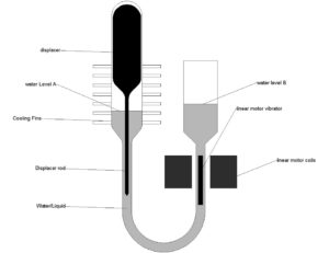
As you can see, there are two chambers connected with a tube. in one of the chamber there is a displacer with a long rod dipped in the liquid piston(water). the unit may be hermitically sealed and pressurized.
You must get familiar with FPSE engines in order to understand the potential merits of this design. Assuming you have done so, i begin:
There is important difference between an FPSE and this VDSE(viscous drive Stirling engine). in an FPSE the displacer is actuated by its own spring or gas spring, independent of piston. actually the displacer is a leader. however in case of VDSE, the piston leads, actuates the displacer and completes its full expansion before actuating the displacer again. this is due to the viscous drag. in this way, the displacer would not obey a sinusoidal relation with time, and hence the PV curve would tend to be more boxy rather than circular, giving some potential extension of PV area.
so the cycle is as follows(from the figure)
- The engine is supplied heat at the top, the little gas above displacer expands, pushing the liquid level A into the tube.
- This movement of liquid, the speed in the tube would be a multiple of speed at level A due to difference in diameters, and thus will drive(viscous drag) the displacer rod at a similar speed.
- The displacer moves and thus remaining gas below displacer moves to the hotter top, increasing the driving pressure.
- The displacer and water level keep moving down, and after full expansion( due to momentum gained by heavy water column), the expansion process stops.
- In case of an FPSE, the displacer would have reversed much before this complete expansion. This is so because the displacer is driven by an actuator(gas spring) different than the piston’s actuator. Thus it moves back to the top pushing the hot gases back to cold chamber even if they still have more potential to expand. This action stops the expansion of the piston and results in the corners of PV graph begin circular or clipped However in the VDSE, the displacer is driven by the same piston(water) and so the things are slightly different.
- The water now flows back from reservoir through the tube into the engine. Only after this motion, the displacer is actuated by the viscous flow of liquid around the displacer rod, and the displacer reaches the top. The hot gases are compressed by the incoming liquid above water surface ‘level A’.
- this compression continues till the momentum of liquid is reduced to zero. Again in case of an FPSE this would not have been possible as the displacer would have started moving downwards much before complete compression is accomplished.
So as you can see, the area under PV curve is potentially increased. the speed of displacer movement is different from piston which cannot be realized in conventional engines(hence the circular PV curve). this (ideally)discrete motion of displacer is what makes this concept very interesting.
As for viscous losses, we are lucky, that these losses dont scaleup with pressure, although the speed of operation must be kept low to minimize these.
———-
Updates:
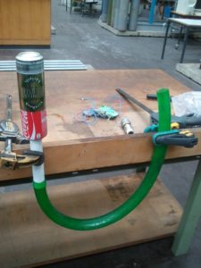
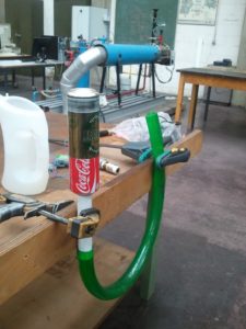
Well i tried the above idea ..here are some pics
..Well the result was the following:
- With the heat sources(hot air gun / propane flame) the flow of water to the other column was too slow to cause any drag. the reasons might be the displacer rod dia is too large, causing a large drag and hence slowing the water flow.
- i have no idea how much water was filled in. next time i will calculate.
- when i removed the green pipe, at the end of experiemnts, there was still some water left in the chamber, and this again proves the 1st point, the displacer rod dia must be smaller so as to permit free flow at high speeds..
well thats all, so i have to modify the dispplacer rod diameter…sorry i dont have the pics of these(displacer and rod). will post shortly.
thanks 🙂


Hi,
Do you have any new information after the last update? Did the chnages you did work out?
thanks & best regards,
Ashwnai
hello Ashwani! no the changes didnt work out. As always in stirling engines there is a compromise that has to be reached. on one had i want enough viscous force to move the displacer, and on the other hand i dont want the flow to be resisted in the channel. these are quiet conflicting, with only solution being that the displacer should be super lightweight to be affected by slight movements. however i thinking about slightly complex designs, where the displacer rod totally blocks the channel at particular times of the cycle. thus this wont be anymore a viscous driving but more of pressure driving. also if this can be true in liquid it can be true for air, and this is very interesting…
also im working on friction as a drive system. with the knowledge that static friction is higher than kinetic friction, if we have a piston with a displacer rod passing through, just like a beta engine, the displacer is affected by piston motion. think about this and see if u can come up with a simple idea, i think mine is simple and i await your thoughts…after some time i will upload the idea here…lazy now :p